How to Choose the Right Steel Frame for Your Facility
Selecting the right steel frame engineering requires matching your facility's span, load, and climate needs to a specific structural system. This guide outlines a step-by-step process for evaluating columns, beams, bracing, and connections to ensure performance and cost control.
- Match the structural system to the building's span, height, and load requirements before selecting materials.
- Engage a structural engineer early to review loads, deflection limits, and connection design.
- Verify that the steel frame engineering account for local wind, snow, and seismic codes.
- Check connection detailing and corrosion protection to prevent long-term structural failure.
- Review shop drawings and field measurements to confirm the design matches the as-built structure.
Define Your Facility Requirements
Start with the physical demands of the project. List the clear span, roof slope, height, and occupancy type. Note the contents: pallet racks, mezzanines, heavy equipment, or stored goods. Identify the site conditions, including soil bearing capacity, flood zone status, and access for crane lifts.
The span dictates the primary members. A 40-foot span might use a simple portal frame, while a 120-foot span usually requires trusses or glulam-steel hybrid systems. The load defines the section sizes. A warehouse with 150 psf of stored goods needs heavier beams than a cleanroom with light partition walls.
Document these inputs in a single sheet. This becomes the baseline for all steel building design decisions. If the requirements change later, the structural engineering calculations must be redone.
Begin the requirements list by measuring the actual floor plate. Do not assume the span is the same as the column spacing. Measure the distance between the center of the interior columns and the center of the exterior columns. This measurement defines the clear span. Record the roof slope in inches per foot. A 2/12 slope is standard for most metal roof panels, but a 1/12 slope requires specific panel profiles and fastening patterns.
Define the height limit. This includes the distance from the finished floor to the bottom of the roof purlin, and the distance to the bottom of the roof beam. Mechanical ducts, sprinkler heads, and lighting fixtures all consume vertical space. If the ceiling height is tight, the roof structure must be designed to accommodate these obstructions without reducing usable floor area.
List the stored materials. Do not just write “warehouse.” Specify the weight of the heaviest pallet, the number of pallet levels, and the location of the heaviest concentration. A forklift lift height determines the minimum racking height. A mezzanine floor requires additional design loads on the beams and columns. A heavy machine tool requires a dedicated foundation and isolation from the main frame.
Identify site conditions. Soil bearing capacity is determined by a geotechnical report. If the soil is weak, the foundations must be larger or deeper. Flood zone status dictates the elevation of the floor slab and the protection of electrical panels. Access for crane lifts requires clear space for the crane boom and counterweight. A site with a tight entrance may require a smaller crane or a different erection sequence.
Evaluate Structural Systems
Compare the common steel frame options for your span and height. Each system has distinct advantages and limitations.
| System | Typical Span | Best For | Main Constraint |
|---|---|---|---|
| Portal Frame | 40 to 80 ft | Single-story shops, light industrial | Height limits, lateral stiffness |
| Truss Frame | 80 to 150 ft | Long-span warehouses, aircraft hangars | Connection complexity, erection time |
| Moment Frame | 20 to 60 ft | Multi-story offices, parking garages | Deflection control, high connection loads |
| Braced Frame | 40 to 100 ft | Seismic zones, long spans | Interior columns, clear span reduction |
| Hybrid System | 60 to 120 ft | Mixed-use facilities | Integration complexity |
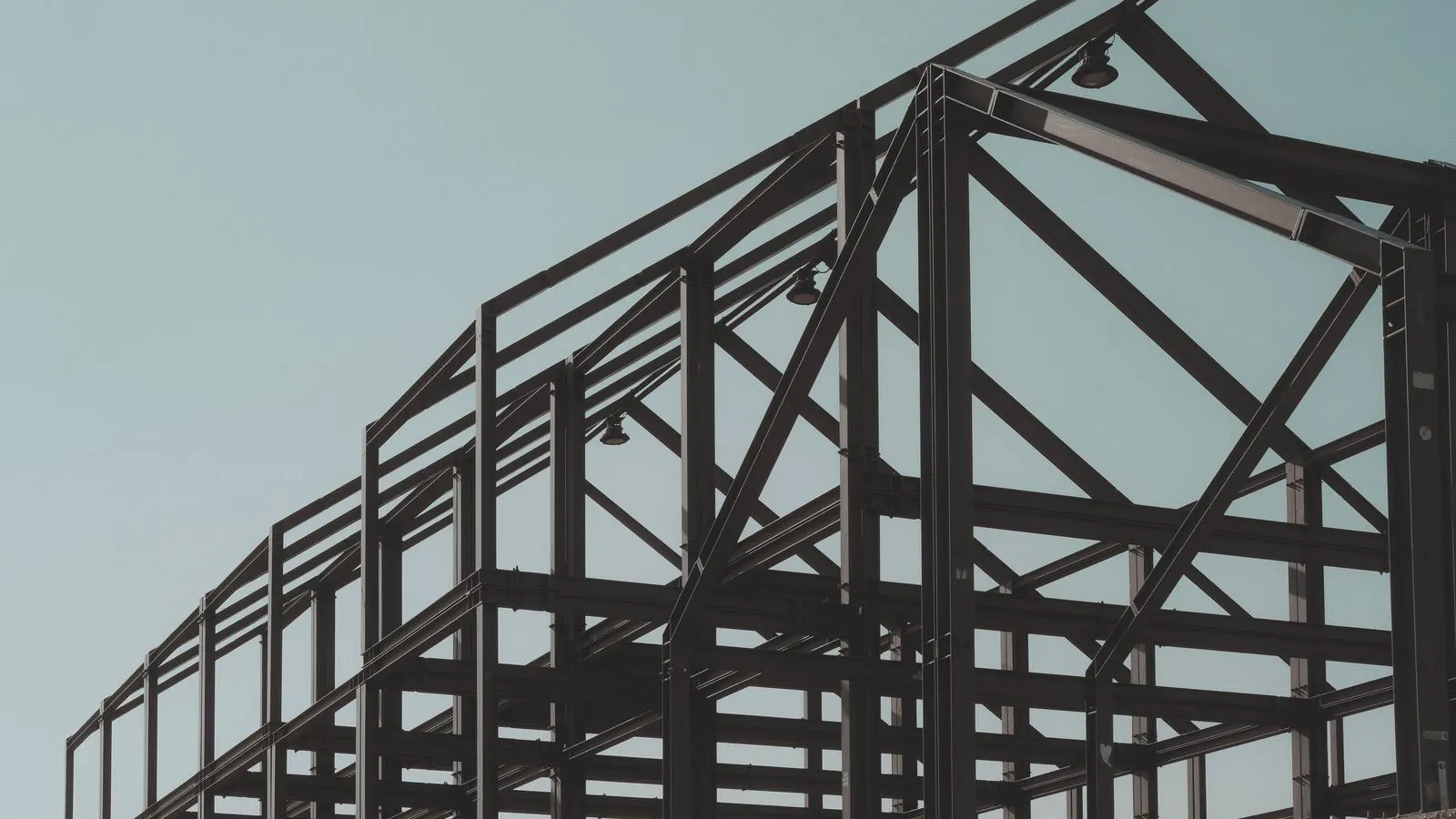
A portal frame uses rigid connections at the top to resist wind and seismic forces. It is economical for short to medium spans. A truss system uses triangular members to span long distances with lighter materials. It requires more connections but reduces member size. A braced frame adds diagonal members to resist lateral loads. It is often used in high-rise or seismic applications.
Match the system to your primary constraint. If clear span is the priority, choose a truss. If budget is the priority for a short span, choose a portal frame. If seismic resistance is the priority, choose a braced frame or moment frame.
A portal frame relies on the stiffness of the connections. The top of the column and the beam act as a continuous beam. This system is simple to fabricate and erect. It uses fewer connections than a truss. However, the members must be large enough to resist the bending moments created by wind and seismic loads. In tall buildings, the portal frame may require heavy members to limit deflection, which can increase cost.
A truss frame distributes loads through axial forces in its members. The top chord is in compression, and the bottom chord is in tension. This efficiency allows for lighter materials over long spans. However, a truss has many joints. Each joint is a potential point of failure if not detailed correctly. Erection is more complex because the truss must be assembled in place or hoisted as a complete unit. If it is hoisted as a unit, the crane capacity must be sufficient for the entire truss weight.
A moment frame resists lateral loads through strong moment connections. It is commonly used in multi-story buildings where clear floor space is needed. It does not rely on bracing, so it allows for open interiors. However, moment connections are complex and require precise fabrication. Deflection control is a major design challenge. The frame must be stiff enough to limit sway, but strong enough to allow plastic deformation during seismic events.
A braced frame uses diagonal members to resist lateral forces. It is very efficient in terms of material usage. The bracing takes the lateral load directly to the foundation. However, it reduces clear span because the bracing members occupy space. It is also less flexible in terms of interior layout.
A hybrid system combines elements of different systems. For example, it may use a portal frame for the lower levels and a truss for the roof. It is used in mixed-use facilities where different zones have different span and height requirements. The integration of different systems requires careful coordination of connections and load paths.
Assess Load Path and Member Selection
Trace the load path from the roof to the foundation. Roof loads transfer to purlins, then to beams or trusses, then to columns, then to foundations. Every member in this path must be sized for the load it carries.
Check the primary members. Columns must resist axial load and bending. Beams must resist bending and shear. Trusses must resist axial tension and compression in their members. Purlins must support the roof deck and resist wind uplift.
Size the members using the applicable building code. The code specifies load factors, material properties, and design criteria. An engineer will calculate the required section sizes based on the load path. Do not rely on manufacturer default sizes. The default sizes are based on typical loads, not your specific load case.
The load path must be continuous. There should be no gaps in the structural elements. If there is a gap, the load must be transferred through a different member. This secondary load path may not be designed for the load.
Roof loads include dead load, live load, snow load, and wind load. Dead load is the weight of the roof deck, purlins, and insulation. Live load is the weight of maintenance personnel and stored materials. Snow load depends on location and roof slope. Wind load depends on building shape, height, and exposure.
Purlins are the small beams that support the roof deck. They are usually C-sections or Z-sections. They must be spaced to limit deflection. Typical spacing is 4 to 8 feet on center. The purlin size depends on the roof deck type and the load. A standing seam roof deck requires stronger purlins than a corrugated roof deck.
Beams and trusses carry the purlin loads to the columns. They must be sized to resist the bending moment and shear force. The section size depends on the span and the load. A wider flange beam is more efficient for bending than a narrow flange beam. A truss is more efficient for long spans because it uses material only where it is needed.
Columns carry the beam loads to the foundation. They must resist axial load and bending. The column size depends on the load and the slenderness ratio. The slenderness ratio is the ratio of the effective length to the radius of gyration. A slender column is more prone to buckling. A stocky column is more resistant to buckling.
Foundations support the columns. They must transfer the column loads to the soil. The foundation size depends on the soil bearing capacity and the load. A shallow foundation is used for good soil. A deep foundation is used for poor soil.
Verify Connections and Bracing
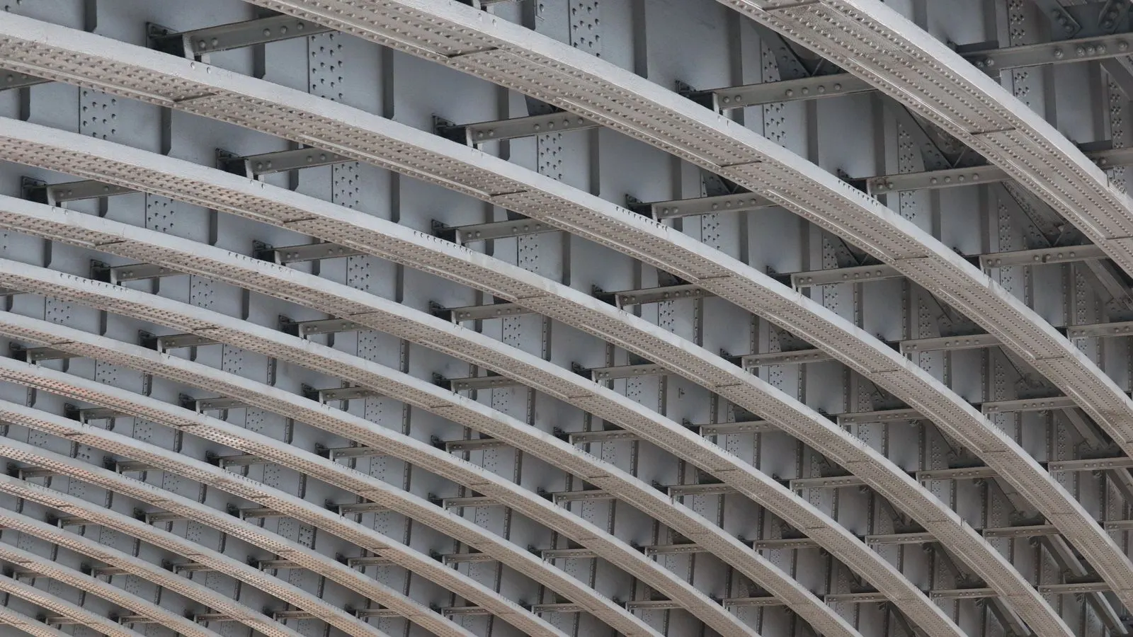
Connections are the weak point in most steel structures. A strong beam and column fail if the bolted or welded connection is undersized. Review the connection design for every major joint.
Check the base plates. They must transfer column loads to the foundation without excessive bending. Check the column-to-beam connections. They must resist shear, moment, and torsion. Check the truss connections. They must transfer axial loads from one member to the next.
Add bracing where the design requires it. Lateral bracing resists wind and seismic forces. It can be added as diagonal members, shear walls, or rigid frame connections. Without adequate bracing, the frame will sway under lateral loads. This causes deflection, cracking in non-structural elements, and potential collapse.
Connections are the critical part of the structural system. The strength of the structure is limited by the weakest connection. A bolted connection must have enough bolts to transfer the load. The bolt size, number, and grade must be specified. The hole diameter must be large enough to allow for field adjustment. The connection plate must be thick enough to resist bearing and shear.
A welded connection must have enough weld size and length. The weld size depends on the load and the material. The weld class must be specified. A fillet weld is used for thin members. A groove weld is used for thick members. The weld must be inspected after fabrication.
Bracing resists lateral loads. It is usually added in pairs to resist loads in both directions. The bracing members must be sized to resist the lateral load. The bracing connections must be strong enough to transfer the load to the main frame. The bracing must be continuous from the roof to the foundation.
Consider Environmental and Corrosion Protection
The site environment affects material selection and connection detailing. Coastal sites have salt-laden air. Industrial sites have acidic fumes. These conditions accelerate corrosion.
Specify the steel grade. Standard structural steel is usually A36 or A992. For high-strength applications, use A572 or A992. For coastal applications, use weathering steel or apply additional protective coatings.
Specify the coating system. Galvanizing provides long-term protection. Painting is common for interior applications. Epoxy priming and polyurethane topcoats are typical for exterior applications. Specify the coating for all exposed surfaces, including inside the hollow sections.
Corrosion protection is a long-term cost item. It is not just a coating. It is a system. The steel grade, the connection type, and the maintenance plan all affect the corrosion performance.
A36 steel is a low-carbon carbon steel. It is easy to weld and form. It is suitable for most structural applications. A992 steel is a high-strength low-alloy steel. It has a higher yield strength than A36. It is used for long spans and heavy loads. A572 steel is a medium-strength low-alloy steel. It is used for intermediate applications.
Weathering steel forms a protective rust layer when exposed to the atmosphere. This rust layer slows further corrosion. It is not painted. It is used for exterior applications where maintenance is difficult. It is not suitable for indoor applications or coastal sites with heavy salt exposure.
Galvanizing involves coating the steel with zinc. The zinc protects the steel by sacrificial corrosion. It provides long-term protection with low maintenance. It is suitable for both indoor and outdoor applications. It is more expensive than painting but requires less maintenance.
Painting involves applying a coat of paint to the steel surface. It provides a barrier against corrosion. It is common for interior applications. It requires more maintenance than galvanizing. It is suitable for indoor applications where the environment is controlled.
Epoxy priming and polyurethane topcoats are typical for exterior applications. The epoxy primer provides adhesion and corrosion protection. The polyurethane topcoat provides UV resistance and color. This system is durable and long-lasting.
Review Seismic and Wind Design
Local codes dictate the design loads for wind, snow, and seismic activity. The structural engineering must account for these loads. A building designed for a low-wind zone will fail if placed in a high-wind zone.
Check the wind load. The wind pressure varies with height and exposure. The roof shape affects the uplift. A peaked roof has different uplift than a flat roof. The engineer will calculate the wind load based on the building code.
Check the seismic load. If the building is in a high-seismic zone, the frame must be designed to resist lateral forces. This may require moment frames, braced frames, or special connection detailing. The connections must be ductile enough to deform without breaking.
Wind load is a critical design parameter. It determines the size of the bracing and the strength of the connections. The wind pressure varies with height. It is higher at the top of the building. It also varies with exposure. An open site has higher wind speeds than a dense urban site.
Roof shape affects uplift. A peaked roof creates a vortex that reduces pressure on the roof surface. A flat roof creates a uniform pressure. The uplift pressure can be higher than the dead load. The purlins and roof deck must be designed to resist uplift.
Seismic load is a lateral force. It causes the building to sway. The frame must be designed to resist this sway. In high-seismic zones, the frame must be ductile. It must be able to deform without breaking. This requires special connection detailing. The connections must be able to rotate and deform.
Final Verification and Field Checks
Before construction begins, review the shop drawings. Compare the shop drawings to the structural engineering calculations. Confirm that the member sizes, connection types, and bracing locations match the design.
During erection, verify the field measurements. Check the column plumbness, beam level, and connection alignment. If the field measurements deviate from the shop drawings, stop and notify the engineer. Do not proceed with the erection.
After erection, inspect the connections. Check the bolt torque, weld quality, and coating condition. Check the bracing for proper tension. Check the foundation for proper bearing. These field checks ensure that the as-built structure matches the engineered design.
Shop drawings are the final design document. They show the exact size, shape, and connection of every member. They are based on the structural engineering calculations. They must be approved before fabrication.
Field checks are critical. The shop drawings are based on ideal conditions. The field conditions may be different. The column may be out of plumb. The beam may be out of level. The connection may be misaligned. These deviations must be checked and corrected.
Bolt torque is a critical check. A bolt that is under-torqued will not transfer the load. A bolt that is over-torqued may crack the steel. The torque must be checked with a calibrated torque wrench.
Weld quality is a critical check. A weld that is under-sized or under-fused will not transfer the load. The weld must be inspected by a qualified inspector. The weld must meet the code requirements.
Coating condition is a critical check. A coating that is thin or damaged will not protect the steel. The coating must be inspected for thickness and adhesion. Any defects must be repaired.
Common Mistakes in Steel Frame Selection
Selecting a frame based on price alone leads to overloading. A cheaper frame may require heavier members or additional bracing to meet the load requirements. This negates the cost savings.
Ignoring the load path causes connection failures. If the load path is not continuous, the connections will carry unintended loads. This leads to premature failure.
Skipping the environmental assessment causes corrosion. A frame designed for an inland site will corrode in a coastal site. This reduces the member size and weakens the structure.
Relying on generic calculations without a local engineer leads to code non-compliance. Local amendments to the building code can change the load factors, material properties, and design criteria. A generic calculation may not meet the local requirements.
Price is not the only factor. A cheaper frame may require more maintenance, more bracing, or more steel. It may also have a shorter life. The total cost of ownership must be considered.
The load path must be continuous. If there is a gap, the load must be transferred through a different member. This secondary load path may not be designed for the load. This leads to failure.
The environment must be assessed. A frame designed for an inland site will corrode in a coastal site. This reduces the member size and weakens the structure. The frame must be designed for the specific environment.
The local code must be followed. Local amendments can change the load factors, material properties, and design criteria. A generic calculation may not meet the local requirements. A local engineer must review the design.
Verification Step
After the shop drawings are approved, perform a final verification. Compare the shop drawings to the structural engineering calculations. Confirm that all members, connections, and bracing match the design. Check the material certificates for the steel grade and coating. Check the connection details for bolt torque and weld quality. If any deviation is found, stop and notify the engineer. Do not proceed with the erection until the deviation is resolved.
The final verification is a critical step. It ensures that the as-built structure matches the engineered design. It is a quality control step. It is a safety step.
The shop drawings must be compared to the structural engineering calculations. Every member, connection, and bracing element must match. Any deviation must be identified and resolved.
The material certificates must be checked. The steel grade must match the design. The coating must match the design. The certificates must be retained for the project records.
The connection details must be checked. The bolt torque must be checked. The weld quality must be checked. The bracing tension must be checked. The foundation bearing must be checked.
If any deviation is found, stop the erection. Notify the engineer. Resolve the deviation. Do not proceed until the deviation is resolved. This ensures that the structure is safe and code-compliant.
Frequently asked questions
What is the difference between a portal frame and a truss frame?
A portal frame uses rigid connections at the top to resist lateral loads and is best for short to medium spans. A truss frame uses triangular members to span long distances with lighter materials and requires more connections.
How do I know if my facility needs a braced frame?
If your facility is in a high-seismic zone or requires a long span without interior columns, a braced frame is likely necessary. The structural engineer will determine the bracing type based on the local code and site conditions.
Can I use a standard steel grade for a coastal facility?
Standard structural steel can be used for a coastal facility if it is properly coated. Galvanizing or a high-performance coating system is recommended to prevent corrosion. Weathering steel is also an option.
What is the most common cause of steel frame failure?
Connection failure is the most common cause of steel frame failure. If the connections are undersized or improperly detailed, they will carry unintended loads and fail before the primary members do.
Do I need a structural engineer for a small steel building?
Yes, a structural engineer is required for all steel buildings. The engineer will calculate the load path, size the members, and design the connections to meet the applicable building code.