What Is a Steel Building Design Blueprint?
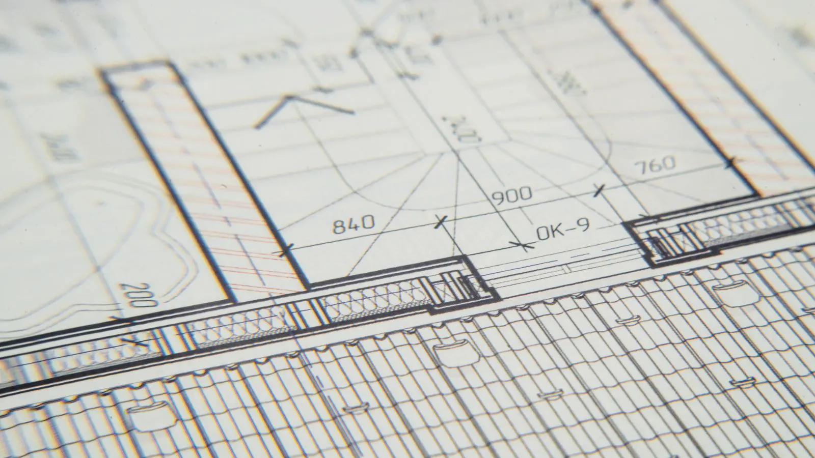
A steel building design blueprint is a technical set of drawings produced by a structural engineer. It defines the frame layout, member sizes, connection details, and load assumptions. These documents serve as the primary instructions for fabrication and erection, directly affecting material costs and construction risk.
- A blueprint is more than a visual sketch; it is a legal and technical instruction set for the contractor.
- The structural engineering documents define the exact size and grade of steel members.
- Connection details within the drawings determine the final assembly method and labor cost.
- Missing or ambiguous notes in the blueprint can cause field modifications that increase project costs.
A steel building design blueprint is the primary technical document that guides fabrication and erection. It is not a sketch of the building shape. It is a detailed set of instructions produced by a professional engineer. These documents tell the fabricator exactly which steel members to cut and how to join them.
For a buyer or project manager, understanding these documents is a practical necessity. The drawings determine the quantity of steel used. They define the connection points where the roof, walls, and floor meet. When the documents are clear, the project moves smoothly from the shop to the site. When they are vague, the field crew must guess, which slows work and raises costs.
What is a structural engineering document?
Structural engineering documentation is the collection of technical drawings and reports that define the skeleton of a building. It is a specific subset of the total architectural package. While an architect draws the walls, windows, and interior finishes, the structural engineer defines the frame.
This documentation typically includes several distinct types of sheets.
- Foundation plans: These show where the steel columns sit on the concrete. They define the size of the concrete pads or footings required. A typical plan will label the centerline distance between columns and the depth of the embedment.
- Frame plans: These show the location of the main columns and beams from a top-down view. They often include grid lines, such as A-1, A-2, B-1, to help the field crew locate specific members during erection.
- Elevation views: These show the building from the outside, detailing the height of the walls and the slope of the roof. They show the relationship between the structural frame and the roofline.
- Connection details: These are close-up sketches of the specific metal plates and bolts used to join the members. They show the bolt pattern, the thickness of the gusset plates, and the weld symbols.
- General notes: These pages list the steel grades, bolt specifications, and safety factors used in the design. They also specify the tolerance for member straightness and the required surface preparation for painting.
The structural engineering documents act as the bridge between the building concept and the physical material. They translate the load requirements into specific steel shapes.
How do load assumptions affect the design?
The blueprint reflects the loads the building must support. A structural engineer does not just draw lines. They calculate how much weight the frame must carry.
The primary loads to consider are dead load and live load. Dead load is the constant weight of the building itself. This includes the steel frame, the roofing panels, the wall panels, and the insulation. A standard metal roof assembly might weigh between 1 to 2 pounds per square foot, depending on the panel profile and insulation type. Live load is the weight that changes. It includes snow on the roof, people on the floor, and stored inventory.
Wind loads also drive the design. The engineer considers the direction and speed of wind in the specific location. This determines how the columns and bracing must be arranged to resist lateral movement. In coastal areas or exposed ridges, wind pressures can be significantly higher than in sheltered valleys. The engineer uses local data to determine the design wind speed.
These calculations result in specific member sizes. A column in a high-wind zone might be larger than the same column in a sheltered valley. The blueprint reflects these local conditions. The drawings are not generic. They are tailored to the specific site and the specific use of the building.
Reading the member size callouts
Once the loads are calculated, the engineer selects the steel. The blueprint lists these selections using standard size designations.
A typical callout might read HSS 6x6x3/4. This notation tells the fabricator exactly what to order.
- HSS stands for Hollow Structural Section.
- 6x6 indicates the cross-section is six inches by six inches.
- 3/4 indicates the thickness of the steel wall is three-quarters of an inch.
Other common designations include W shapes for beams and HSS for columns. W shapes are open sections with a flange and a web. They are efficient for bending loads. HSS are closed sections. They are efficient for compression and torsion. The specific size affects the cost. A larger section uses more raw material. It also weighs more, which changes the crane requirements during erection.
The blueprint is the source of truth for these sizes. If the shop orders a different size than what the drawings specify, the project is in trouble. The connections will not fit. The structural capacity will not match the calculated safety. A fabrication error here is not a minor adjustment. It requires cutting, re-drilling, and potentially re-fabricating the entire member.
How connection details affect construction
The connections are where the steel members join. This is the most critical part of the blueprint for the field crew.
There are two main types of connections. Welded connections and bolted connections. Most prefabricated steel buildings use bolted connections for the main frame. This allows the shop to pre-assemble the parts. It also allows the field crew to make adjustments if the foundation is slightly out of alignment.
The connection details show the layout of the holes and the size of the bolts. They specify the type of bolt, such as a high-strength bolt or a standard structural bolt. They also show the gusset plates that transfer force between the column and the beam. A gusset plate is a flat steel plate that connects two members at an angle. It must be thick enough to resist the shear force between the members.
If a connection detail is unclear, the field crew may make a field modification. This is often more expensive than the original design. A field weld or a cut-and-drill operation takes time. It disrupts the workflow. The blueprint must be precise to prevent this. A clear detail shows the bolt diameter, the hole diameter, the clearance, and the edge distance. It also shows the required torque for the bolts.
Worked Example: A Simple Bay Design
Consider a standard steel building with a span of 40 feet. The roof slope is 2/12.
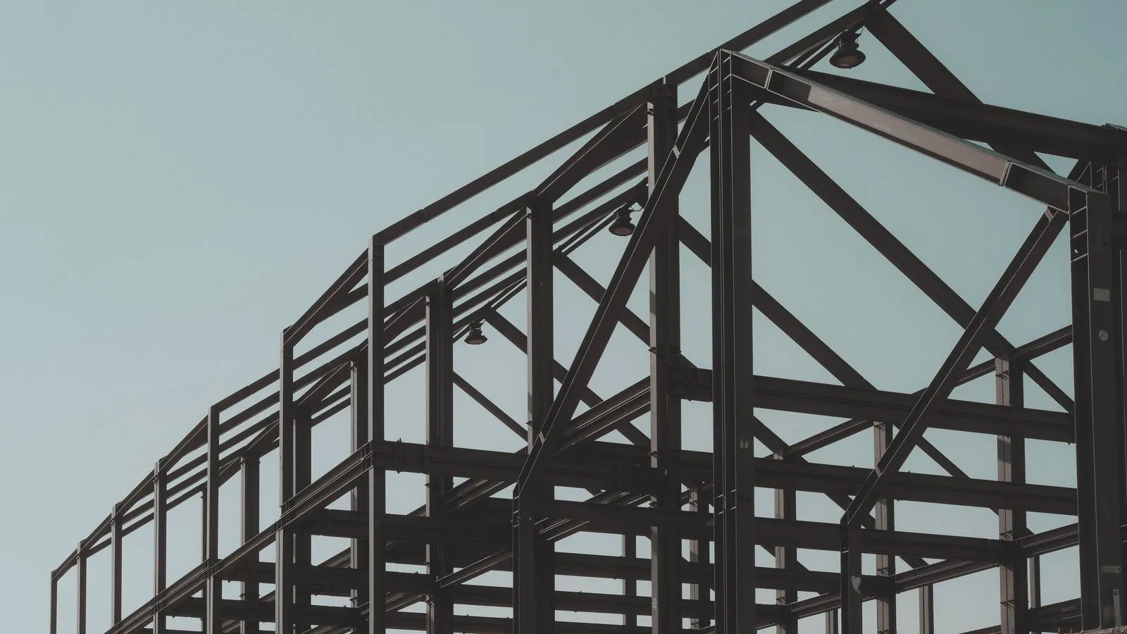
The blueprint shows the main purlins running parallel to the long wall. The purlins are spaced every 4 feet. The main gable trusses support the purlins. The trusses are made of HSS columns connected by W shapes at the top.
The drawing shows a bolted base plate at the bottom of the column. This plate sits on the concrete foundation. The top of the column connects to the truss using a gusset plate.
The structural engineering documents include a note that specifies the steel grade as A36. This is a standard carbon steel grade. It is widely available and easy to work with. The yield strength of A36 steel is 36 ksi. This is a standard reference point for most light commercial buildings.
The fabrication shop receives these drawings. They cut the HSS and W shapes to length. They drill the holes for the bolts. They assemble the trusses in the shop. The field crew then lifts the trusses into place and bolts them to the base plates.
The blueprint is the contract between the designer, the fabricator, and the builder. It defines the exact geometry and material specification for every component. A single missing dimension can halt the entire fabrication line.
Common mistakes in steel building design
Even professional engineering firms make errors. These mistakes can lead to delays and cost overruns.
- Inadequate foundation sizing: If the concrete pads are too small, the columns may tilt. This requires shimming or re-pouring the foundation. Shimming is a temporary fix. It does not resolve the root cause.
- Conflicting dimensions: The architectural drawing may show a window that clashes with a structural beam. The structural drawing must show the clear span for the opening. If the beam cannot be moved, the window must be resized or relocated.
- Missing connection details: A drawing might show a beam and a column meeting, but fail to show how they are joined. The builder must then invent the connection, which is risky. An invented connection may not have the required strength.
- Incorrect steel grade: Using a lower grade steel than specified reduces the load capacity. This is a safety issue and a legal violation. The engineer must specify the grade clearly in the general notes and on each member callout.
Reviewing the blueprint before fabrication is a standard practice. The shop should flag any errors. The engineer should correct them quickly.
How to review a blueprint before fabrication
Buyers should not rely solely on the engineer. They should review the drawings themselves.
Start with the general notes. Check the steel grade and the bolt specifications. Look at the foundation plan. Ensure the column locations match the site layout.
Check the connection details. Look for clarity. If a detail is ambiguous, ask the engineer for a clarification. Do not guess.
The blueprint is the foundation of the project. It defines the scope of work. A clear and accurate blueprint leads to a smooth construction process.
Frequently asked questions
Does a steel building blueprint include electrical plans?
No. The structural engineering documents focus on the frame and loads. Electrical, plumbing, and HVAC are separate disciplines with their own drawings.
Can a steel building be built without a structural engineer?
In many jurisdictions, a professional engineer must seal the drawings for a building permit. Building without them can lead to safety risks and legal penalties.
What is the difference between a shop drawing and a blueprint?
A blueprint is the design document from the engineer. A shop drawing is the fabrication drawing from the steel maker. They are usually similar, but the shop drawing includes manufacturing details like hole patterns.
How long does it take to get a blueprint?
It depends on the complexity of the building. Simple structures may take a few weeks. Complex facilities with multiple spans may take longer.
Can I modify the blueprint after fabrication?
It is possible, but it is expensive. Changes to the blueprint after the steel is cut require re-fabrication. It is best to finalize the design before the shop starts work.